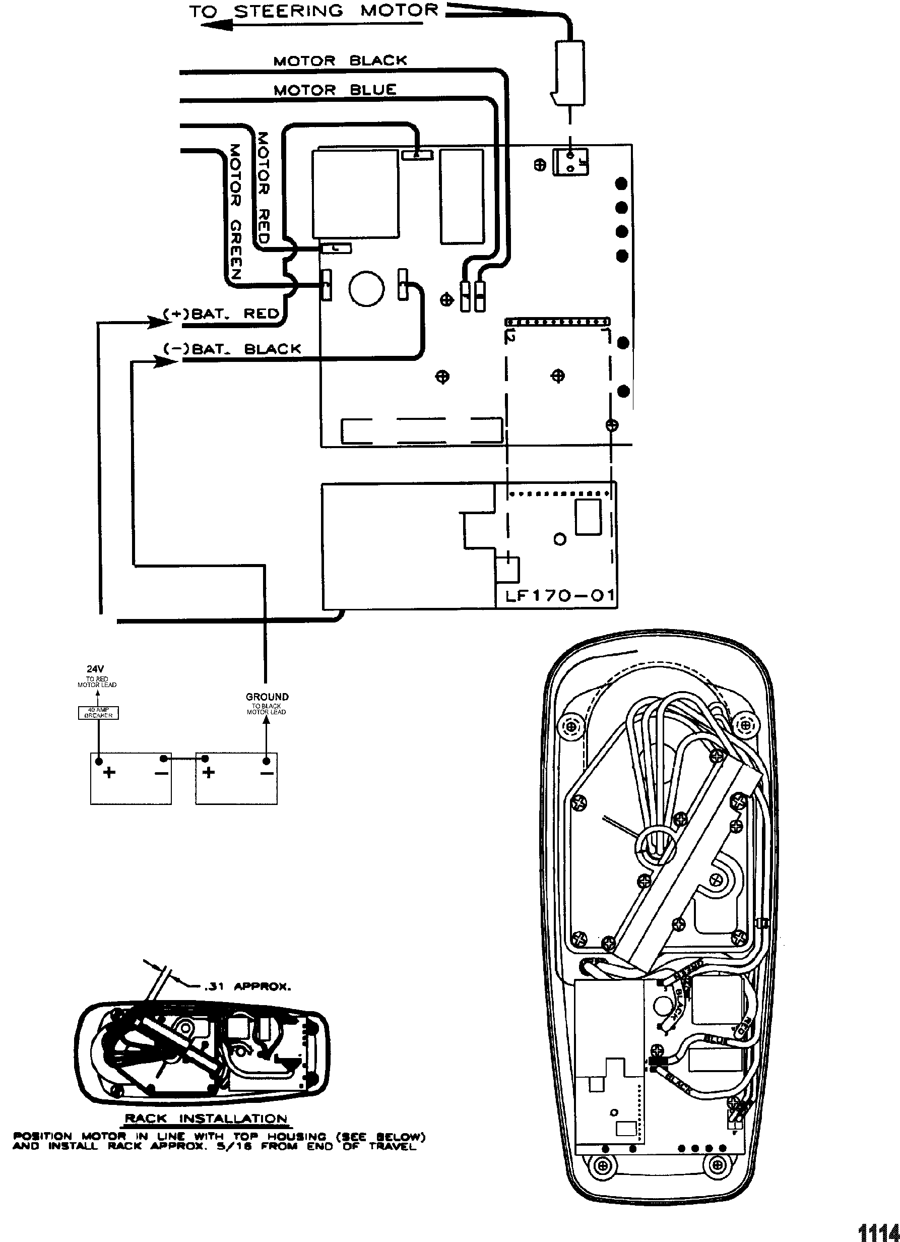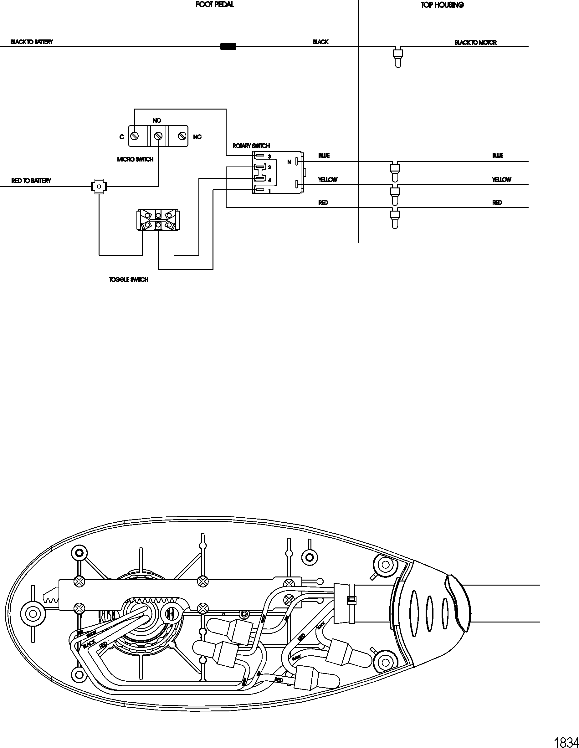
Wire diagram motorguide trolling motor. November 30, 2018 1 0.

You will need a diagram of your switch panel to get all those wires connected correctly.
Motorguide trolling motor wiring diagram. When connecting each jacketed 24 vdc trolling motor battery configuration with (2) 12 vdc batteries. For instance , if a module is usually powered up and it sends out a new signal of half the voltage and the technician will not know this, he would think he has a challenge, as he would. Using a battery connector cable, connect the positive terminal of your first battery to the negative terminal of your second battery.
Wire diagram motorguide trolling motor. Trolling motor motorguide 600 series wire diagram model 652 12 volt perfprotech com. So the lower unit was in perfect working condition (this alone is a $300 part for saltwater tm).
Foot pedal motorguide trolling motor wiring diagram from i0.wp.com. Owners manuals and instructions for your motorguide products & accessories. Similar to infuriating to remove, replace or repair the wiring in an automobile, having an accurate and detailed motorguide 12 24 volt trolling motor wiring diagram is critical to the execution of the fix job.
Motorguide is excited to introduce the new x3 trolling motor, designed to deliver better performance and durability for anglers looking for the best value in the 40 to 70 pound thrust range. The trouble really is that all car is different. 40+ motorguide trolling motor wiring diagram california.
Wiring diagram comes with a number of easy to adhere to wiring diagram directions. Motorguide trolling motor wiring diagram motorguide free. Motorguide trolling motor wiring diagram.
Wellborn assortment of motorguide 12 24 volt trolling motor wiring diagram. Minn kota trolling motor plug. A trolling motor is an innovative boating tool for maneuvering a fishing boat through the water without its outboard engine.
Each battery has a positive terminal which is red in color and a negative terminal which is black in color. The motorguide battery charger is available in 4 models and can be used in 12 and 24 volt. Motor thrust diagram wiring lb fwd rev guide trolling motorguide control freshwater x3 bow foot mount rating stars.
Mercury trolling motor motorguide 700 series 1998 up wire diagram model 736 12 volt outboard parts van s sport center. Downrigger schematics $ 0.00 0 items; Motorguide trolling motor wiring diagram:
Many times, a mechanic is burdened unnecessarily because of wrong or antiquated wiring. Definitely an impressive new system from motorguide! Loosen the two terminals on the circuit breaker supplied with the trolling motor.
While small and medium trolling motors use a single 12v marine battery, larger trolling motors use larger 24v and 36v systems, and require 2 or 3 marine batteries, accordingly. Ranger boat battery wiring diagram 3 wire alternator wiring diagram. To do this easily, the batteries need to be placed side by side.
A single trick that i use is to print out a similar wiring picture off twice. Mercury trolling motor motorguide 700 series 1998 up wire diagram model 736 12 volt outboard parts van s sport center. Trolling motor motorguide pro series wire diagram wireless models 12 24 volt perfprotech com.
Motorguide trolling motor wiring diagram: Motorguide trolling motor wiring diagram. A wiring diagram is a simplified conventional photographic depiction of an electric circuit.
24 and 36 volt wiring diagrams trolling motor wiring diagrams while small and medium trolling motors use a single 12v marine battery larger trolling motors motorguide trolling motor wiring. When you use your finger or even the actual circuit along with your eyes, it’s easy to mistrace the circuit. Jul 07, · my motorguide trolling motor is white, black, red.
Just avoid the green blue purple and red wires to the right and that box they hook to those are part of my electric steering modification. 6 pin trailer plug wiring diagram. To properly read a electrical wiring diagram, one offers to learn how the particular components in the system operate.
Mercury motorguide trolling motor parts by model series hvf and hvt oem diagram for wire hvf5000 hvf5200 12 volt boats net Slide the black wire over the terminal and tighten it down. A wiring diagram is a kind of schematic which makes use of abstract pictorial signs to reveal all the.
You will need a diagram of your switch panel to get all those wires connected correctly. Standard industrial plc wiring, white is neutral, black positive, and green earth ground. These larger motors and multiple batteries are wired in a series pattern, and optimally, the circuit breaker should be wired within 4 of.
Home / trolling motor schematics / motorguide motor schematics. 24v only motors will have just two wires. November 30, 2018 1 0.
Volt mercury outboard motor parts trolling motorguide pro series 600 wire diagram model hvt3000 hvt3200 12 767 24 1999 electric 12v lazer ii installation wiring. The 24v motor is ideal for anglers who are looking for a better fishing experience at a more affordable rate than the 36v motor. 12 24v trolling motor wiring diagram.
Run the black wire from the trolling motor to the boat battery and loosen the negative terminal with a wrench. Trolling motor wiring diagrams while small and medium trolling motors use a single 12v marine battery, larger trolling motors use larger 24v and 36v systems,. For more information on wiring batteries, please review the conductor gauge and circuit breaker sizing table on.
Installation diagrams 48 volt system the following schematic outlines the necessary. Wiring trolling motorguide motor diagram 12v brute question schematic pedal switch schematic1 motors crappie. Old motorguide trolling motor parts wiring diagram.
Trolling motor motorguide series wire diagrammodel volt. Mg speed coil test (442.5k) motorguide 530 (1.8m) motorguide 536 (1.9m) motorguide 540 (1.8m) Print the electrical wiring diagram off plus use highlighters in order to trace the signal.
Slide the red wire from the motor over one of the terminals and tighten it down. These devices are available in three models: